top:
day week month all

Fluiddynamics

Community for : 1.7 years

Talk about and share fluid dynamics, theories, CFD, random musings, anything related to flow, and the study thereof.

Owner: usedoilanalysis

Mods:
usedoilanalysis


14
Magnetic fields change the behaviour of atoms altering reactions     (www.youtube.com)
submitted by usedoilanalysis to Fluiddynamics 1.6 years ago (+14/-0)
4 comments last comment...
11
2d flow.     (Fluiddynamics)
submitted by usedoilanalysis to Fluiddynamics 1.6 years ago (+11/-0)
16 comments last comment...
Doesn't exist, it's trying to simplify and approximate the truth. Flow is 5 dimensional, we assume 2 orthogonal axis of spin, and we call the other stuff secondary flow. Flow is locally structured in 3 dimensions, and translated in another 2. Locally structured in x, y, and z planes, and the other 2 dimensions are borrowed from electromagnetism, divergence and curl. Divergence is basically pressure gradient, and curl is basically vorticity.

Aerodynamicists create formulas and approximations to encapsulate all 5 dimensions of airflow. Prandtl's lifting line theory, Martin Kutta's theories regarding circulation, and the subsequent Kutta-Jukowski theorem. Which is really just a description of flow around a cylinder, with an applied Fourier transformation. As we all know Fourier transformations are 2-d projections of more complex phenomena.

The problem is we are pea-brained, it's difficult for us to see the nested donuts in airflow, and the 5 dimensions they encompass. It's bad enough we can't see the wind, but worse our tools for analyzing it are dependent on butchered approximations.

A while ago I saw a new propeller design, and then it hit me like a ton of bricks.

https://www.youtube.com/watch?v=MNnB_50Z20I

This thing is just ribbons of a torus.

https://i.ytimg.com/vi/px5kZn_hPbU/maxresdefault.jpg

The vortex ring is a torus, a non-destructive interference pattern. The vortex ring encapsulates all 5 dimensions of flow. X,Y,Z planes of symmetry, divergence and curl, all in one.
9
You can watch the storm in semi-real time     (cdn.star.nesdis.noaa.gov)
submitted by usedoilanalysis to Fluiddynamics 1.6 years ago (+9/-0)
3 comments last comment...
8
High fidelity CFD simulation of helicopter rotor in forward flight     (www.youtube.com)
submitted by usedoilanalysis to Fluiddynamics 1.5 years ago (+8/-0)
4 comments last comment...
7
Hand to elbow relationship.     (Fluiddynamics)
submitted by usedoilanalysis to Fluiddynamics 1.5 years ago (+7/-0)
3 comments last comment...
If you lock your lower body, and turn your palm from up to down, or down to up(so that your thumb rotates 360 degrees), you see your elbow moves in a swinging motion. Now if you turn your palm, and restrict the movement of your elbow, you see that your entire body needs to rotate in order for the elbow to remain stationary. This is the secret of taiji, the isolation of either the elbow, waist, or knee in order to force a full body rotation. This is how you generate maximum power and leverage with your body.
6
Curry nigga drops CFD knowledge about compressor blade aerodynamics.     (youtu.be)
submitted by usedoilanalysis to Fluiddynamics 1.7 years ago (+6/-0)
8 comments last comment...
https://youtu.be/NhZ08el9IfQ?t=2743

This stuff applies well to anyone dealing with turning vanes, or strakes to guide flow. Often underestimated or outright missed by CFD is the 3D nature of the flow and secondary flow structures between strakes/compressor rows.
5
Hurricane Ian     (Fluiddynamics)
submitted by usedoilanalysis to Fluiddynamics 1.6 years ago (+5/-0)
20 comments last comment...
Looks like it's just going to park itself in the gulf of Mexico near Tampa, until it dissipates. The eye isn't going to make landfall until Friday of this week. All the Tampa people beware of flooding more than strong winds.
5
Aerodynamics, an introduction.     (Fluiddynamics)
submitted by usedoilanalysis to Fluiddynamics 1.4 years ago (+5/-0)
4 comments last comment...
In order to understand fluid dynamics, I felt it would be helpful to share how air behaves under different circumstances. This will be a multi-part series, where I describe air and why it flows the way it does. I will try to keep things simple and easy to understand, with little to no math. Any equations I present will be explained in simple terms that are intuitive.

Air is capable of creating incredible forces, it keeps planes up in the air, it can crush steel drums, it keeps water as a liquid, how is this possible? This is because air has mass, at sea level the pressure is nearly constant and there is a pressure of ~14.7 pounds over every square inch of area. This pressure is pressing on all objects from all sides, as above so below the saying goes. It is this fact that we use and exploit in order to create aerodynamic forces. Air wants to fill everything with itself, and whenever something moves through the air, the physical object removes air for a split second, and as a result air will try to fill that displacement. This is true of fluids in general.

You may have heard the term "nature abhors a vacuum" this is especially true of air. It is the motion of air attempting to fill that vacuum that creates aerodynamic forces. Then following this logic, air moves as a result of the difference in pressure, the default atmospheric pressure, or what is known as "static pressure" will move towards anything that is less than this standard pressure.

Where it starts to get complicated is the path the air takes to fill that difference in pressure. Logic would tell you that the most efficient path between two points is a straight line, so naturally you would think that air follows the path of least resistance, I.E. a straight line. However this is not the case, air rarely if ever flows in a smooth straight line except under the most carefully controlled conditions. By and large, air takes a curved path, that is its preferred path of motion, why does air do this?

The primary reason is that air has mass, and as a result it is subject to inertial and viscous forces. Thus we have the Reynolds number, which accounts for the inertial and viscous forces in a packet of air and serves as a rough estimate of when a flow becomes turbulent. The Reynolds number is estimated as the density of the fluid times the velocity, times the distance the fluid covers, over the viscosity of the fluid. The smaller the Reynolds number the more likely the flow is to be laminar, linear and smooth. Inversely, the greater the Reynolds number the more likely it is to be turbulent and chaotic.

This means that increasing the size of the air packet, or parcel, increasing the velocity of the flow, or its density will give you a greater reynolds number, in other words a flow more likely to be turbulent and chaotic. Inversely the greater the viscosity of air, the lower the reynolds number. Interestingly, the viscosity of air increases with temperature, and its density decreases. Thus temperature has a big influence in the tendency of air to become chaotic and turbulent, however this relationship is not linear.

Another reason why air likes to take curved paths is a result of the speed air moves at, this is because as mentioned previously air has mass, as a mass of air moves, it displaces air, and as a result lowers the static or default pressure of a given volume. Bernouli tried to capture this in his famous equation. As a result of moving or displaced air in a given volume the surrounding air will move to fill that slightly lower pressure from all sides. The easiest way for something to surround something from all sides is a sphere. However, if the air keeps moving, the leading part of the displaced air will have higher pressure as it butts or collides with the standard or static pressure, and a lower pressure on the trailing side. Thus, the tendency of air to fill that low pressure will be curved.

In the next part, I'll cover more advanced aspects of airflow, including why vortexes happen, thank you for your time.
4
Secondary flow.     (www.youtube.com)
submitted by usedoilanalysis to Fluiddynamics 1.6 years ago (+4/-0)
2 comments last comment...
https://www.youtube.com/watch?v=IEBvAG48UFE

Secondary flow is defined as flow that does arises from, but does not move in the same direction as the primary or main flow in a system.
4
Viktor Schauberger     (www.youtube.com)
submitted by usedoilanalysis to Fluiddynamics 1.6 years ago (+4/-0)
0 comments...
4
Using vibration to reduce drag.     (www.carthrottle.com)
submitted by usedoilanalysis to Fluiddynamics 1.6 years ago (+4/-0)
4 comments last comment...
https://www.carthrottle.com/post/can-you-improve-a-cars-aerodynamics-by-making-it-vibrate/

This follows experiments in the lab where piezoelectric actuators were used to induce traveling waves along the surface of an airfoil. It was found that low amplitude traveling waves between 6-10hz would destructively interfere with vortex shedding. This reduced drag and allowed greater AoA.
4
Manly P. Hall: Magnetic Fields of the Human Body     (www.youtube.com)
submitted by usedoilanalysis to Fluiddynamics 1.5 years ago (+4/-0)
1 comments last comment...
4
Expansion fans on exhaust valve seats.     (Fluiddynamics)
submitted by usedoilanalysis to Fluiddynamics 1.3 years ago (+4/-0)
29 comments last comment...
During the blowdown phase, as the exhaust valves open, the gas entering the exhaust ports is just about supersonic, especially at low lift angles. This supersonic flow is susceptible to expansion fans.

https://en.wikipedia.org/wiki/Prandtl%E2%80%93Meyer_expansion_fan

This is why radiused exhaust valve seats and tulip valves with a rounded valve edge on the CC side helps flow. Expansion fans accelerate flow and are isentropic, that means without generating entropy in the way that a normal or oblique shockwave does. Not only does this simplify the calculations, but the expansion fans have very little losses. Typically a shockwave acts as a barrier for air, and causes non-reversible losses. An expansion fan on the other hand eliminates MOST, not ALL losses up to the accelerated velocity of ~Mach 1.4.

The angle needed to achieve M1.4 via expansion fans is ~9-10 degree steps. The air that flows through the seat and the valve face is flowing through a series of angles, if these angles can be kept to 9-10 degrees, one can dramatically lower losses on exhaust blowdown.

This is a lot harder to achieve on the intake valve(s) because the flow there never goes above Mach .55 maybe locally at low lifts with high VE it could get close to M=.6-.7 or the trans-sonic regime. Although for port injection, one also has to consider wet flow(ie fuel) and as a result limits the angles that can be used depending on the engine application. So while a full radius job on the intake will flow more CFM, it won't necessarily make more power, because smooth angles not only allow air to stick, but also any other fluid, such as fuel.

https://i150.photobucket.com/albums/s92/chippievw/F1technical/F1technicalintakeport002_zps9d11215f.jpg

Here you can see a cross section on the valve seats of a Cosworth V-10 F1 engine. Exhaust on the right, intake on the left. You can see the curve on the exhaust port is more pronounced compared to the relatively straight intake port, which only has a slight curve near the valve seat. This turn is necessary to guide airflow across the seat and into the combustion chamber, as well as to allow fuel and some air to separate from the wall to avoid pooling. Of course, at 18,000rpm the air is already mostly turbulent and will mix the crap out of the fuel. However at part throttle and lower rpm, the flow can be so laminar that fuel sticks to the walls and falls out of suspension.

For this reason engines that operate at lower RPMs and are undervalved(ie not enough valve for the combustion chamber), will benefit from 5 discreet angles on the intake side, particularly if the engine is carbureted.

https://www.speednik.com/wp-content/blogs.dir/1/files/2013/05/Valves_2.jpg

While such a setup will flow a bit less than a full radiused valve seat, they typically work better in terms of combustion stability, and can help to limit flow reversion. On the exhaust seats, there is usually no fuel being burned(unless you're doing anti-lag), and you want the flow to leave the CC as fast as possible, doing full radius helps. You don't have much reversion on the exhaust seats, because the exhaust manifold is at a much lower pressure, and the overlap helps maintain the pressure gradient towards the exhaust.

With direct injection, since you don't have to worry about fuel in the intake, the rules change somewhat, and what is beneficial for the exhaust side, is also beneficial for the intake side as fuel is injected directly into the CC. When boost is introduced the similarities and ability to exploit expansion fans starts to work on the intake side because air density has a small but measurable effect on flow velocity. This can leave the air smack dab in the transonic region especially at low lift levels. Since valves open and close, the valves are at low lifts twice, and high lift once.
4
How a vortex increases flow velocity in a pipe.     (Fluiddynamics)
submitted by usedoilanalysis to Fluiddynamics 12 months ago (+4/-0)
5 comments last comment...
Suppose you have a pipe with x amount of air flowing through it. Suppose the flow is nice and laminar throughout the pipe, it's velocity distribution will look something like this.

https://files.catbox.moe/ysa5y8.jpg

The flow near the walls will be slower because the drag from the wall's boundary layer and the moving flow slows it down, while it moves faster near the center of the pipe because the greatest mass of air is moving uniformly carrying its momentum forward with no wall to obstruct it.

Now, what happens if we put a vortex in the middle of that pipe?

https://files.catbox.moe/yk9slc.jpg

The vortex itself is occupying the middle of the pipe, as long as the vortex maintains its integrity, the air cannot pass through the vortex it must go around it. Therefore the vortex is acting like a flow restriction, reducing the cross sectional area of the pipe. The shear stress of the vortex squeezes the air against the walls of the pipe, and reduces the cross sectional area of the pipe. In order to maintain continuity, the flow speeds up, and the pressure in the pipe drops.
4
Bladeless Hydro Turbine, low head, fish safe     (www.youtube.com)
submitted by happytoes to Fluiddynamics 8 months ago (+5/-1)
0 comments...
https://www.youtube.com/watch?v=ArQE3SB0kyM

Non-technical. Video illustrates principle with paper cup and ping pong ball. Decent video of actual installations.
3
RB18 floor update.     (files.catbox.moe)
submitted by usedoilanalysis to Fluiddynamics 1.7 years ago (+4/-1)
0 comments...
https://files.catbox.moe/phr2r0.png

This update has improved the car performance. The update I'm pointing out is the fillet radius at the bottom of the strakes. This builds up the pressure on the leading face of the strakes, and keeps the high pressure from bleeding into the low pressure side. This increases the vorticity of the flow downstream. Everyone else puts the bottom fillet radius in the direction of airflow.

https://files.catbox.moe/1gic06.webp

The Ferrari for instance tried to go with the flow with their strakes.
3
Magnetron plasma vortex(speaker/headphone warning)     (youtube.com)
submitted by usedoilanalysis to Fluiddynamics 1.6 years ago (+3/-0)
1 comments last comment...
3
Effect of blade tip winglet on the performance of a highly loaded transonic compressor rotor     (www.sciencedirect.com)
submitted by usedoilanalysis to Fluiddynamics 1.4 years ago (+3/-0)
0 comments...
https://www.sciencedirect.com/science/article/pii/S1000936116300383

Very interesting study that shows that using a winglet on the pressure side of a rotor cascade improves rotor performance, particularly by extending the stall point. In other words, the pressure side winglet creates a higher pressure ratio at a lower rotor speed. This is achieved while having a negligible impact on drag.

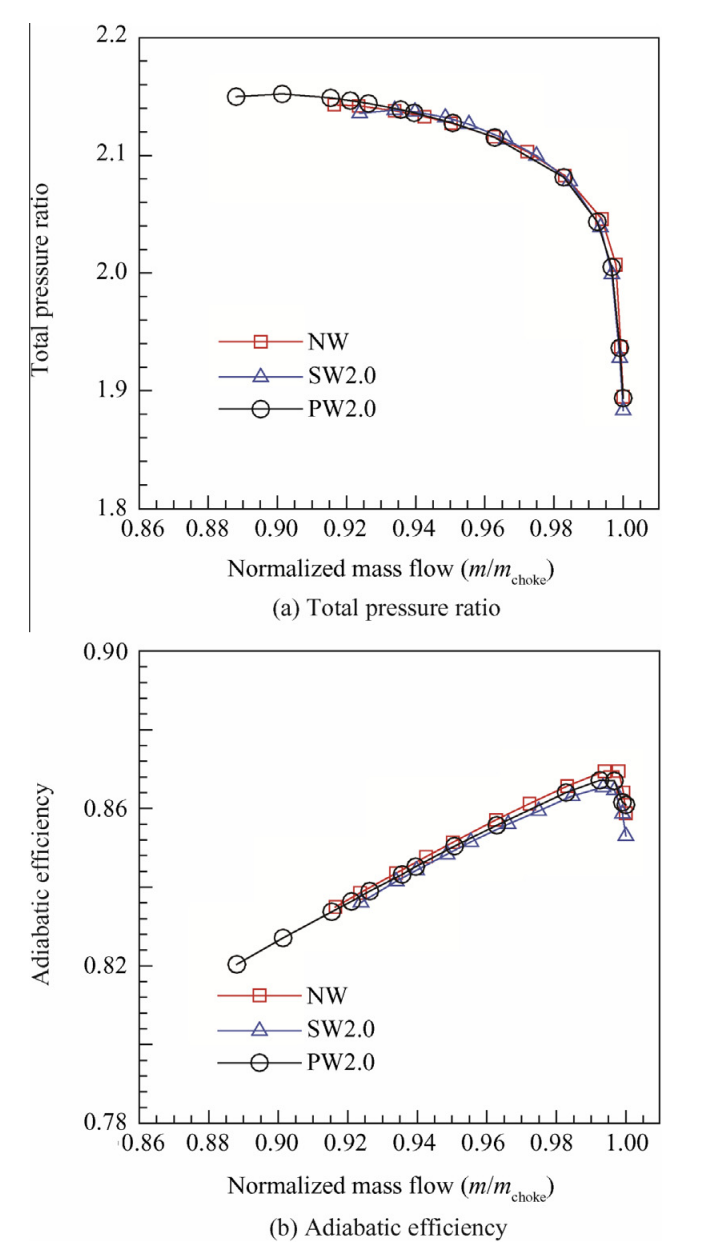
"On the contrary, the
pressure-side winglet greatly improves the stall margin and
introduces only a very small penalty in efficiency. At peak efficiency point, there is an efficiency reduction of about 0.27%.
The predicted penalty in rotor isentropic efficiency is due to
the additional surface offered by tip winglet which increases
the additional skin friction loss. Moreover, the pressure-side
winglet causes a slightly higher pressure ratio near the stall
point relative to the reference case..."

"By applying pressure-side winglet, the stall range predicted
by the present work is extended by 33.74%. This shows a significant improvement in the stall range of the compressor
rotor."

This is highlighted in this image.
https://files.catbox.moe/37sing.png

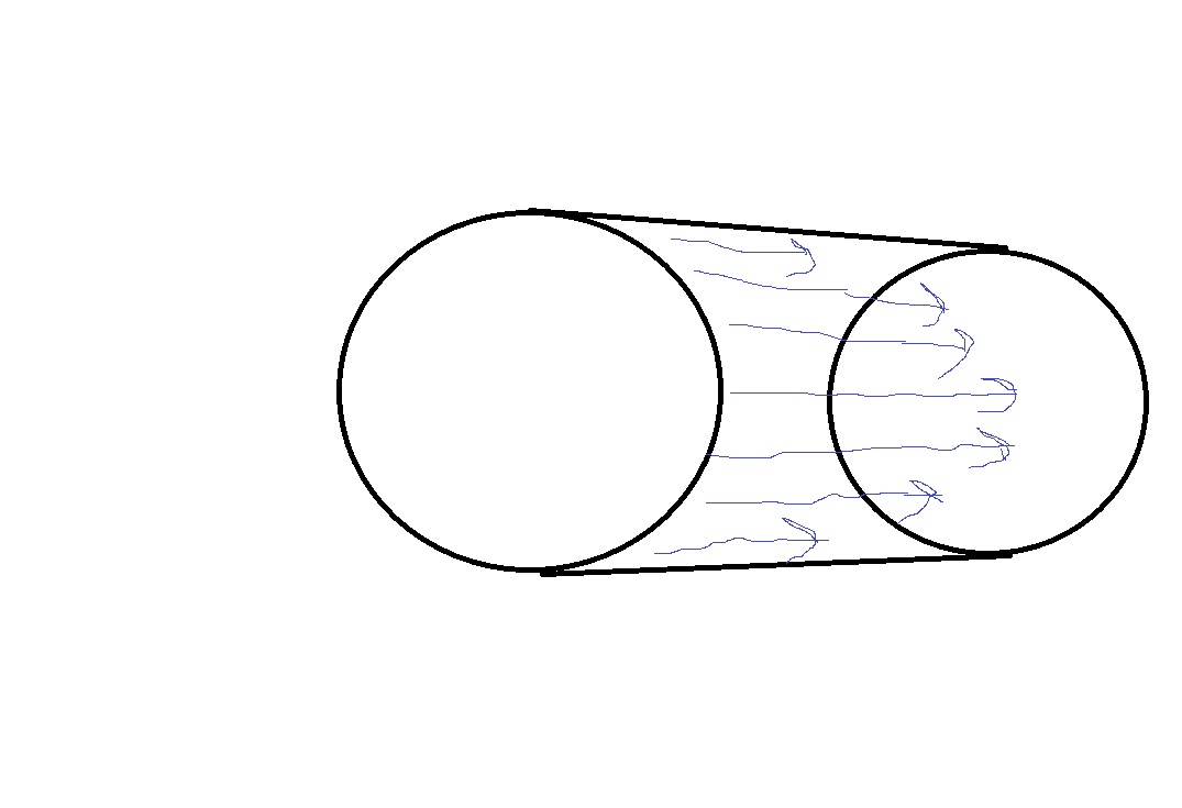
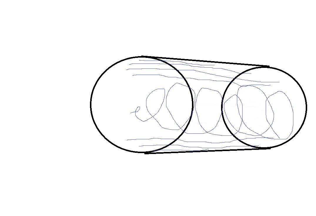
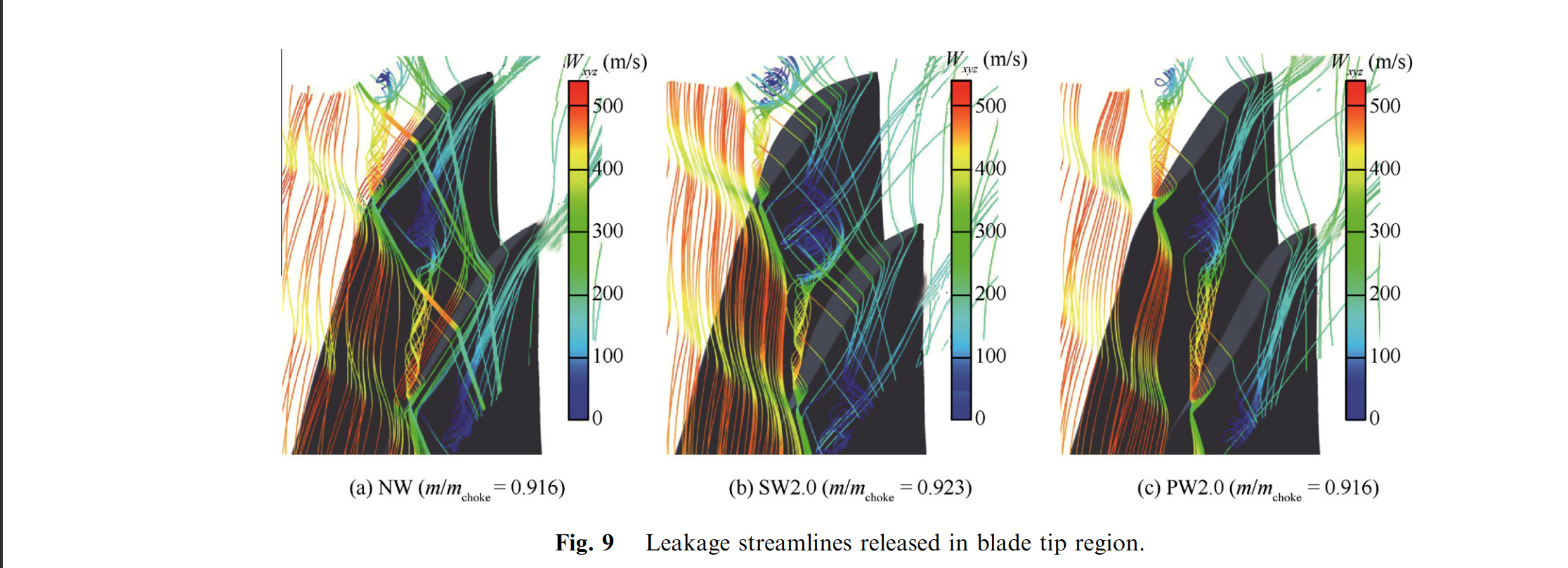
The study further goes on to say

"In the condition with the suction-side winglet
applied, the shock wave/tip leakage vortex interaction is being
intensified which leads to a stronger change in the tip leakage
vortex structure. It is found that the tip leakage twists seriously
and a spiral type breakdown seems to occur at the middle of
the rotor passage. In the case with pressure-side winglet, the
tip leakage vortex trajectory is more inclined in the streamwise
direction. In addition, the distance from the first tip leakage
vortex appearance at the suction surface to the intersection
with the shock is longer than the corresponding distance in
baseline tip case. With the longer distance, the low momentum
core fluid is reenergized as tip leakage vortex mixing with main
flow."

https://files.catbox.moe/k2fytu.png


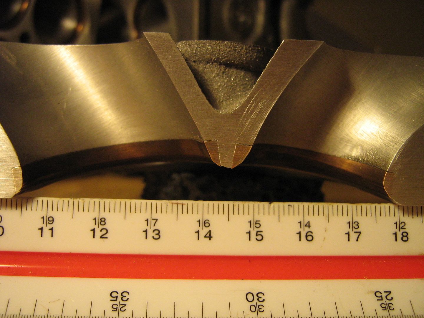
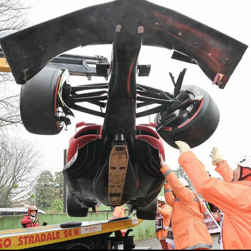
Not complete proof but evidence that pressure side winglets extend the stall range in a wing cascade, this would be useful in something like a current generation Formula 1 car that uses floor fences in a cascade arrangement. The regulations allow the use of the pressure side winglets as there is a 50mm fillet radius that is allowed on these cascades.


https://files.catbox.moe/ce7igv.jpg

https://www.fia.com/sites/default/files/fia_2023_formula_1_technical_regulations_-_issue_1_-_2022-06-29.pdf

3.5.2 subsection d states
"Once each Floor Fence has been fully defined it is permitted to apply a Fillet at the
boundary between it and the Floor Body, having radius of curvature no greater than
50mm. Such a Fillet would then be considered part of the associated Floor Fence."

As far as I can tell, this means that you can apply a fillet once the floor fence is within the bounds of the actual floor, it makes no mention if the fillet can be applied at the top or bottom of the floor fence.
3
What is a Boundary Layer? | Cause of Boundary Layer Formation | Types and Impact of Boundary Layers     (www.youtube.com)
submitted by usedoilanalysis to Fluiddynamics 11 months ago (+3/-0)
2 comments last comment...
2
The key to the lead left hook.     (Fluiddynamics)
submitted by usedoilanalysis to Fluiddynamics 1.6 years ago (+2/-0)
0 comments...
Is to isolate the motion of the *front knee. There is no one way to do this, but it is very difficult to do.

https://www.youtube.com/shorts/DK9bIkQg4yc

Here you can see a perfect demonstration of the principle in action.

The knee can go up and down, but it cannot wobble side to side, or twist, it must work like a hydraulic jack, only moving up and down.

By loading the front knee with the weight of your torso, you keep the knee from buckling. This allows you to turn the upper torso independently of the lower.

This is in accord with Taoist principles, in order to generate power, there must be a yin yang separation. In this case, the legs are solid, the torso is pliant. That separation delivers great power and knocks the fuck out of the nigger.
2
Electromagnetism - Maxwell's Laws     (youtu.be)
submitted by usedoilanalysis to Fluiddynamics 1.5 years ago (+2/-0)
2 comments last comment...
2
"The Fine Print" Lyrics by King Geedorah     (www.youtube.com)
submitted by usedoilanalysis to Fluiddynamics 1.5 years ago (+2/-0)
0 comments...
2
Modify SB Ford OE iron heads for a 94 HP gain     (www.youtube.com)
submitted by usedoilanalysis to Fluiddynamics 1.4 years ago (+2/-0)
15 comments last comment...
2
2.3 Mazda 4 valve head ported with great improvements     (www.youtube.com)
submitted by usedoilanalysis to Fluiddynamics 1.4 years ago (+2/-0)
0 comments...
2
Recirculation and flow reversal's influence on downstream wake.     (Fluiddynamics)
submitted by usedoilanalysis to Fluiddynamics 1.4 years ago (+2/-0)
0 comments...
Have you ever harnessed the wake of a semi truck, draft it to save gas due to lower air resistance? No you haven't because you have to be impractically close to it.

This is because there is strong flow reversion and turbulent recirculation behind a semi. The recirculation is so strong that it stops the wake from extending very far behind the truck.

Therefore the only way to draft a big ol truck is to ride its bumper. Where the recirculation and flow reversal actually pulls you forward. Similar to how trout use flow reversal behind their scales to swim against the current.

A car with a smooth streamlined wake is the ideal drafting partner. The slow smooth wake extends further behind the car, and affects a trailing car that's further behind.